Clubman Estate Part 5
a 52mm Throttle Body
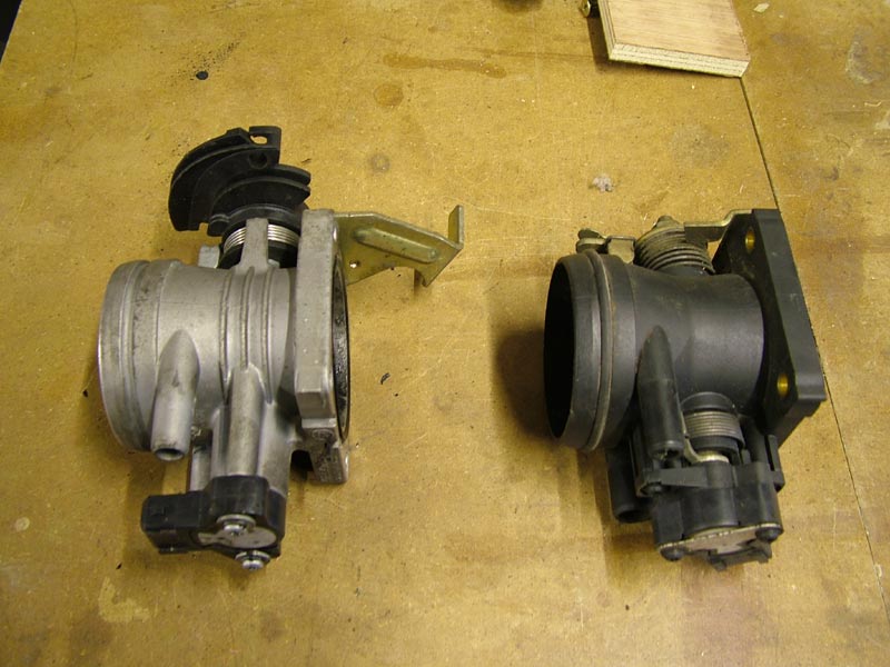
The standard throttle body on the MPI Mini has had a lot of entries on various forums, the main problem seems to be with a sticking butterfly but mostly at higher mileages than mine has done. I assume that the main reason for this is the plastic body distorting due to age/heat/fuel combinations. Anyway mine is still working well, but I keep wondering what it might be like with a little increase in size. There are a few Mini specialists offering an upgrade from the standard 48mm plastic one to an alloy bodied unit of 52mm diameter. This is quite an expensive piece of kit, so I thought I would investigate other possibilities - one would be to make one myself from scratch but as Rover used lots of common parts for many vehicles, it turned out that some of the MG ZR's used a 52mm body which, on investigation looked as if one might fit with a few relatively simple mods. This unit was made by Dellorto and was also fitted to the Lotus Elise and MGF cars also - so used ones should be available.
I soon turned one up at the right price on eBay - avoiding a few which had early bidding wars going on. I used the spare plastic one I had for comparison; this too turned up cheap on eBay complete with manifold, injectors, IACV and all sensors - this stuff WILL get hard to find and pricey.
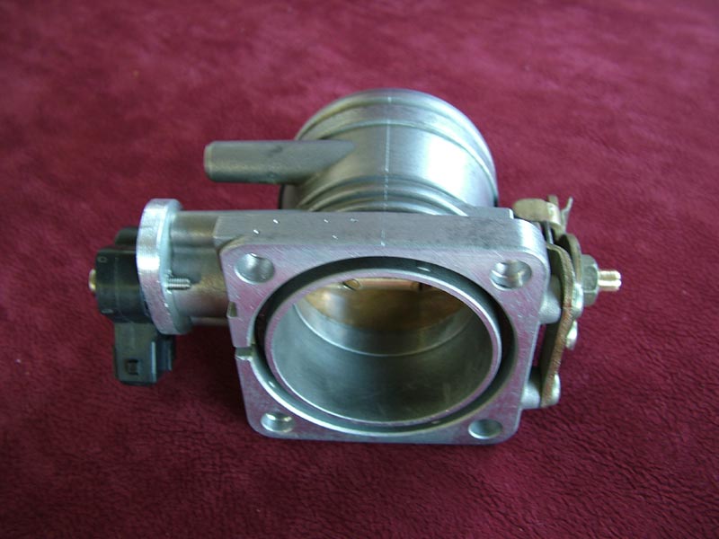
Bingo! same mounting flange, same height, same diameter where the air filter fits over the body. Looks like the only mods will be a new spindle and throttle pot mount.
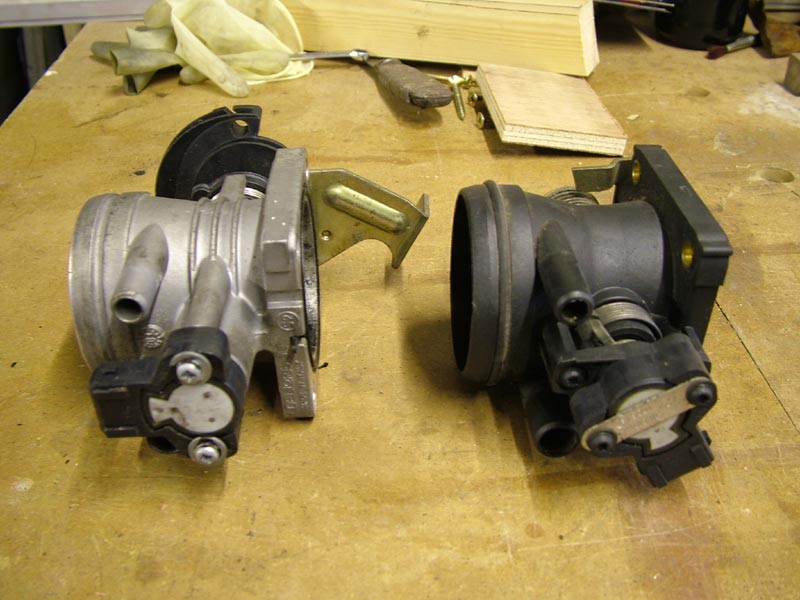
The Throttle pot angle needs to be changed by means of an adaptor plate
....and the Mini quadrant and stop need changing over, plus the stop needs trimming to allow full opening
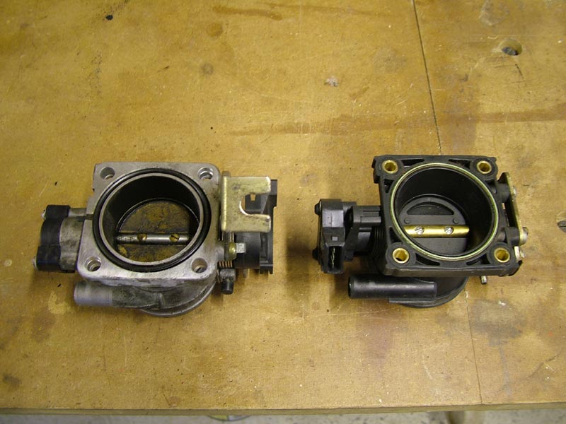
The simple maths of increasing the diameter from 48 to 52 shows a theoretical increase of 17% in throat area, but the real increase is actually 26% as the spindle is smaller on the 52mm unit; 8mm on the alloy body as opposed to 9.5mm on the plastic one. Back in my early days (60's and 70's) of making carbed minis quicker, 'ovalising' the throttle spindle was always a useful extra mod when going from HS2 to HS4.
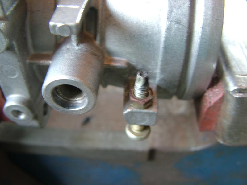
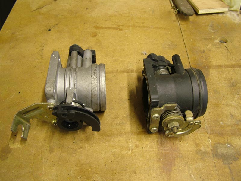
I swapped the original throttle stop screw from the plastic unit as it needs to be a bit longer. Here it is fitted the wrong way round so that I could make adjustments during prep for drilling the butterfly screws; it saved having to disturb the quadrant to get to the screw head. It's now fitted the right way round and the quadrant has a larger area to rest against at closed throttle.
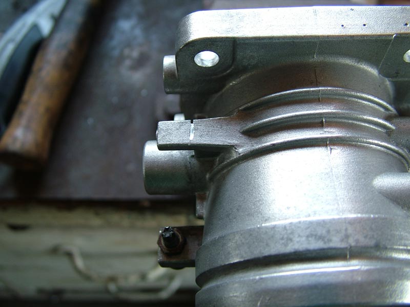
The little piece with the saw-cut needs removing from the body to allow the mini throttle quadrant to swing fully open.
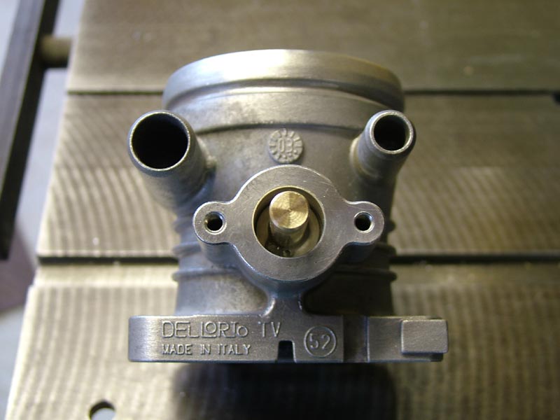
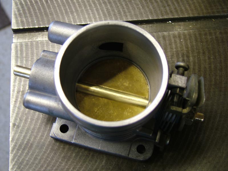
This shows the new throttle spindle in place for checking - the spindle still needs the flat machining on this end to drive the throttle position sensor and the sandwich plate making to mount the sensor. Note that the screw holes on the alloy unit would leave the sensor connector pointing downwards (or upwards), but it needs to point down at about the 8 o'clock position to clear the manifold in one direction and the filter in the other.
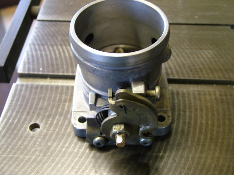
The mini quadrant and MG throttle stop screw in place. The Mini throttle stop plate at the bottom needed a little trimming to allow the butterfly to open fully. The distorted return spring can be seen in this shot - sorted later.
With the butterfly snugly fitted through the spindle and the end float and quadrant clearance checked, it's now time for dismantling to drill and tap the securing holes for the butterfly - the screws will be peened over and loctited to prevent them being eaten if the engine gets hungry! I'll make a little jig for drilling the spindle - as I did when I put the slot in the spindle for the butterfly on the milling machine. I'm not happy with the way the return spring 'squidges' to one side, so I'll make a little top hat bush in nylon to centralise it better. The two air hole spigots (on the filter side of the venturi) are in exactly the same positions as on the plastic unit and also the same diameter - it just gets easier!
I used the original spindle from the alloy body to set the miller up for drilling and tapping the butterfly set screws - they are spaced at 20mm centres and I used a normal slocombe centre drill which conveniently has a 60 degree cone angle for the countersink - the same as the screws. This was followed by drilling through with a 3.3mm drill ready for tapping M4 and then a 4mm drill through the top surface of the spindle to allow the screws to be slipped through before trapping the butterfly. This was followed by rotating the spindle to the correct angle for machining the flat which drives the throttle pot.
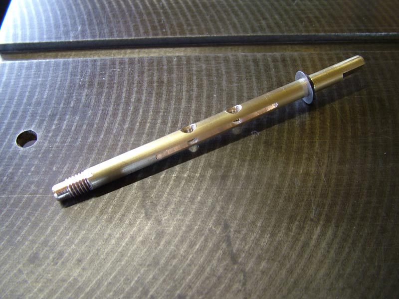
The completed throttle spindle with circlip and washer from the MG unit
Next job was to make the alloy sandwich plate to put the TPS (throttle position sensor) in the correct position relative to the butterfly. A dry assembly run confirmed that all was well, so it was now time to dismantle it all for careful cleaning and lubricating, followed by reassembly with the neoprene spindle seals in place and 'loctite' applied to all threads to prevent any future problems, plus peening the two brass butterfly screws.
Sandwich plate fitted, just needs tidying and the screws shortening
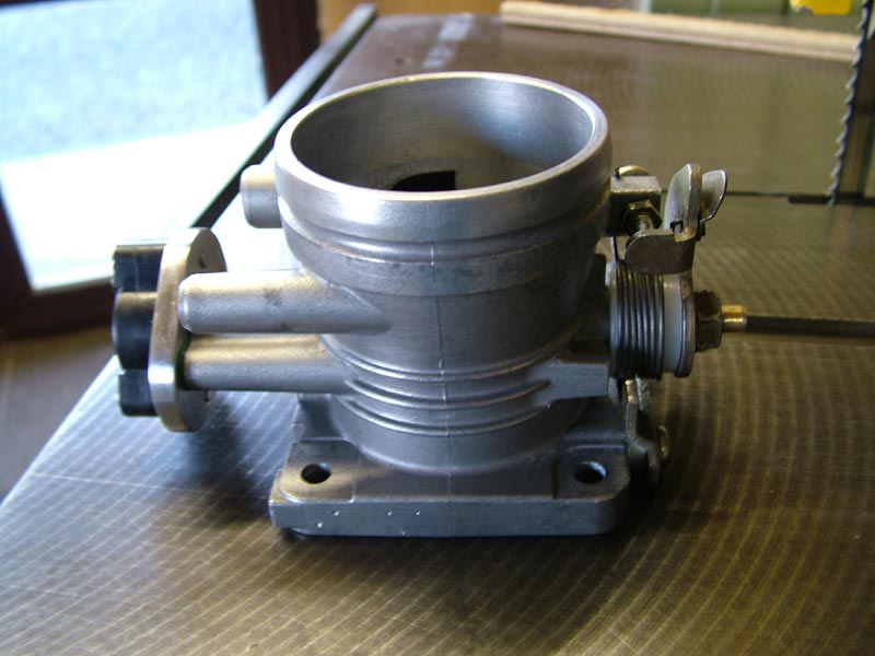
To correct the 'squidgy' return spring, I made up a nylon top hat bush to centralise it - shown here fitted inside the spring on the right hand end.
When fitted, it will be necessary to 'teach' the ECU the new throttle pot readings so it knows what's going on. This is done by switching the ignition on (but not starting the engine), disabling the immobiliser and then rotating the throttle quadrant from fully closed to fully open 10 times slowly (some sources say 5 times). The ECU is not bothered about the exact resistance (within reason) as long as it thinks one position is open and one closed. Now that the intake is larger and it will gulp more air, you might assume the mixture would be weak. However, the Lambda (air/fuel ratio) sensor in the exhaust will detect this and instruct the ECU to increase the injector pulse width to compensate - but there is a limit to how much extra, with this ECU.
In the absence of a rolling road, the fairest test would be to do a few timed runs from 30mph to 60mph in 3rd then 4th on a known stretch of road with the original 48mm body and then repeat it all with the 52mm unit. I'll see if I get some meaningful figures!