Honda CB350 and 400 Four cam chain tensioners
I know that there have been a great many articles already written regarding the cam chain adjustment system on Hondas and especially the four cylinder 350’s and 400’s which have come in for a lot of criticism - sometimes perhaps undeserved. Although many people have condemned Honda for designing a system which in their opinion is not up to the job, like many problems it really is down to ham fisted owners or just pure and simple lack of regular maintenance. The original information from Honda was quite straightforward – slacken the locknut and the adjuster with the engine running at 1200rpm, allow the springs on the adjuster to take up the slack, then tighten the bolt to the CORRECT torque and then tighten the locknut. In the bike’s early life the adjuster was often over tightened, which left a bruise on the adjuster shaft and prevented the adjuster moving under spring tension at the next adjustment attempt. Gradually, as the chain stretched and no adjustment could be made, the chain eventually started its inevitable flapping around and then, as there is very little room between components, the side plates of the chain made contact with the pivot on the adjuster, producing that characteristic rattle. 'They all sound like that Sir' said the bike salesman who looked suspiciously like the young chap who only the previous week was trying to sell me double glazing.
Once this situation has been arrived at, then you have reached the point of no return and the only proper solution is to remove the engine and do a complete crankcase split, as the adjuster unit can only be removed that way, being fastened to the underside of the top crankcase half. Some people have suggested in various magazine articles that removing the blanking plug at the end of the spring loaded pin and using a punch to swing the adjuster further down to tension the chain - sort of manually, is a solution. It will probably work in some cases - but because the springs are still not doing their job, you have no way of knowing for certain that the chain is tensioned correctly and if it has been over tightened, which it could easily be with a tight pivot, then there is no way back and it could result in a broken chain and a wrecked engine. A few years ago, that might not have been too much of a problem as engines were cheap and plentiful but as prices of complete bikes have increased dramatically, then so have engines – and they are harder to find.
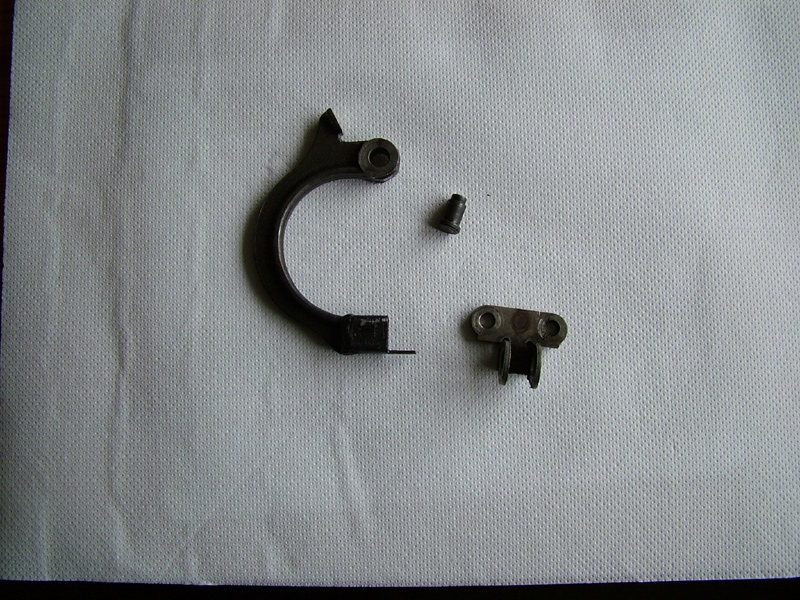
These are the component parts of the adjuster after removing the pivot pin by filing off the tail.
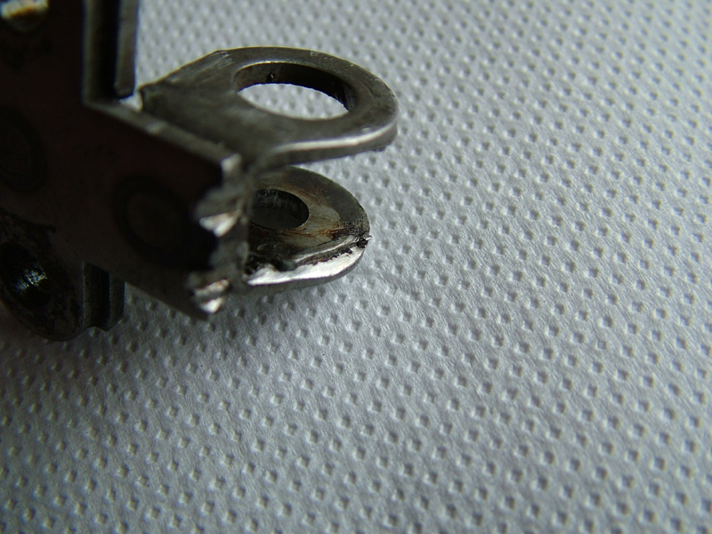
This is a shot of the damaged fulcrum bracket after disassembly - the marks where the chain has made contact are clearly visible, as is the 'bruising' to the sideplate where the metal has been pushed into the gap, effectively locking up the whole mechanism.
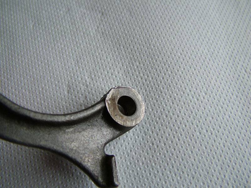
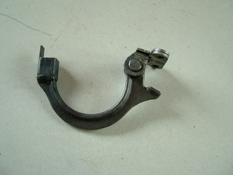
The damage to the arm itself can be seen in this shot and again the bruised metal at the 12 o'clock position The small reduction in diameter is not going to weaken the arm significantly, so those marks are just carefully dressed out with a fine file.
There is a well known supplier of Honda parts who has now started offering a very well engineered unit to replace the original system and although it seems to be a complete solution, it still doesn’t really address the problem of when the adjuster bolt gets over tightened in future. As an engineer I am not really convinced of the need for bronze bushes at the pivot point on this modified unit with such a low angular movement – the original component designed by Honda didn’t seize because it required bushes, but because of it being struck repeatedly by the flapping chain – this new modified design might prevent the pivot from becoming locked if the chain hits it, but it will not make the pusher rod become free again, but there again neither will my method - although I can do mine for virtually nothing, compared with almost £100 including post and vat for this modified one.
On the last few engines I have done, I have removed the adjuster unit and then taken out the riveted pivot pin so that the offending damage can be dressed out and a new pin made and re-fitted. The pin is easily removed by filing the small riveted end off before tapping out with a pin punch, supported over a length of suitably sized tube to allow the pin to escape. The pin is a relatively simple lathe turning job, but the tolerances are fairly critical. It's best for me to not give detailed dimensions, but to leave it to you or your turner to measure what you have and make accordingly. I also machine a small chamfer on the ‘head’ end so that when I rivet the other end over, there is no chance of the head swelling and tightening up. When all is finished, the pivot should move easily under its own weight with no stiffness or play.
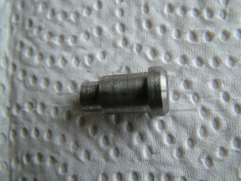
This is the new pin - made in the lathe from just a scrap piece of mild steel - which is all that the original is made from, so that the rivetted end can be formed easily. The head and tail end need to be a good fit in the bracket and the middle section needs to be a running fit in the arm and a few thou longer than the thickness of the arm - this ensures that nothing locks up when you rivet it together. There is plenty of room in the upper crankcase for the extra head thickness I have added to aid riveting. I assemble the bracket, arm and pin after lubricating with Moly 60 paste to aid initial lubrication - should it be a while before I get around to completion.
The riveting process is simple once the pin is fitted and requires just a few blows with the flat end of a small ball-pein hammer to swell the small end of the rivet, followed by a bit of rounding over using the actual ball pein. I also use Loc-tite on the two bolts which hold the adjuster unit to the upper crankcase
This is the completed assembly ready to be fitted to the casing