Norton Model 50 350cc
Part 6
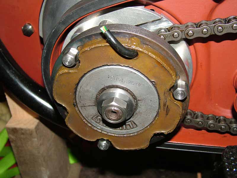
The Primary Drive and Alternator
I had a really odd assortment of Norton clutch bits hanging around from previous projects and other stuff I had purposely bought from eBay and Norvil. It had, like a lot of this bike, never been assembled as a fully working unit, so I turned my attention to making the best clutch I could, without just going out and buying everything. The gearbox is actually from an early Commando, which was in an Atlas frame I got via the late Tony Proud, so the main-shaft is slightly different in length and has a circlip groove machined in it to position the diaphragm clutch body. New main-shafts are available, so I will have to get one of those and then the Commando one will end up on eBay to reduce the impact of the new one. I am using the older multi-plate clutch with a single row primary chain - it's only a 350 single! The gearbox shell mountings are narrower on the Commando, so all that is then needed is a spacer to make up the gap next to the engine plate - a simple alloy plate top and bottom, perhaps requiring machining to thickness - unless there is a piece of scrap of the right thickness somewhere under the bench!
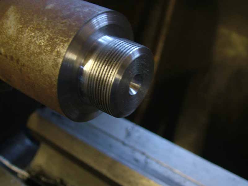
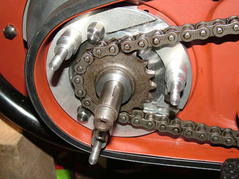
The clutch centre spider I had was really tight on the main-shaft, caused by a few burrs and bruises, but a brief session with a needle file sorted that problem. I decided to make a centre extractor before nipping the centre nut on to the shaft, as it is really difficult to remove without one, you certainly can't use a conventional puller on the clutch basket! The previous owner of this spider had damaged the internal extraction thread slightly - probably by having a sloppy socket on the centre nut when tightening it. I measured the internal thread and as far as I could tell, it was 1-1/4" 20TPI. It would take me ages to alter all of the change wheels and gearing on the lathe to produce this - it was all set up for metric pitches since the last job I did, so I figured that as there are only about 9 threads inside the spider (a bit less than half an inch of thread length), then I could get away with selecting a 1.25mm pitch (The maths - 20 ˟ 1.25 = 25mm, 1" = 25.4mm, error 0.02mm per pitch) - its only for an extractor on a bruised thread at that and will barely bind up over that distance. I did use a 55 degree tool though to allow the flanks to sit close.
A hefty lump of scrap provided the raw material
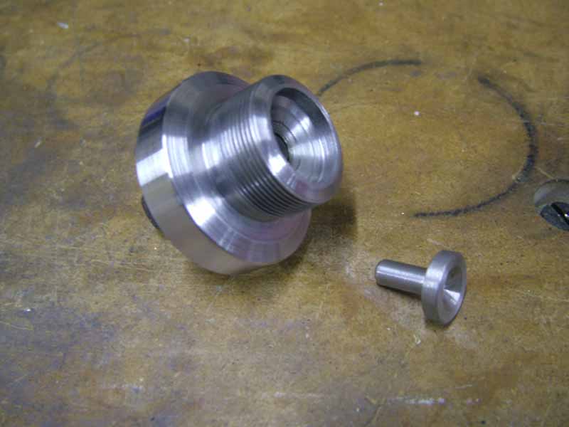
The headed pin on the right slips down inside the gearbox main-shaft (where the clutch push-rod goes) to protect it from the jacking screw end, even though the shaft is hardened.
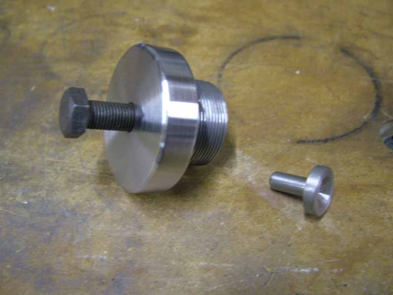
I used a 7/16" UNF bolt in the centre (because I had one!) although I must admit I do prefer UNF for extractors, with their relatively fine pitches to produce high wedge forces. I know you can get metric fine stuff, but that's yet another box of taps and dies needed!
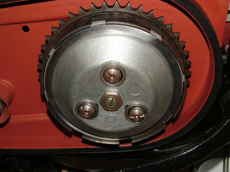
With everything cleaned and checked, it was a relatively easy job to assemble the clutch - bearing in mind I will have to dismantle it all again into big bits after the build up, so that I can paint it all!
It's now time to turn my attention to the alternator, which is a 12 volt 2 wire one which I had some place in a box. The wires on the stator have been cut short, but I can re-loom those - the big problem was that I had no mounting cage and no spacers/bolts/mounting hardware. The cages are available at a price, but I'm on a roll at the moment and enjoying some time in the workshop using the lathe and miller. I'm also spending time on the house in between all of this - no wonder I've no time to go to work!!
I had some 1/2" Dural plate and thought that would do for a mounting ring to which I could attach 3 turned posts to hold the stator plate in the correct position. I band-sawed a disc from the scrap dural sheet with it's centre marked with a dot punch. This was then mounted in a 4 jaw chuck with the jaws reversed and a 'dummy' centre placed between the tailstock centre and the dot punch on the plate.
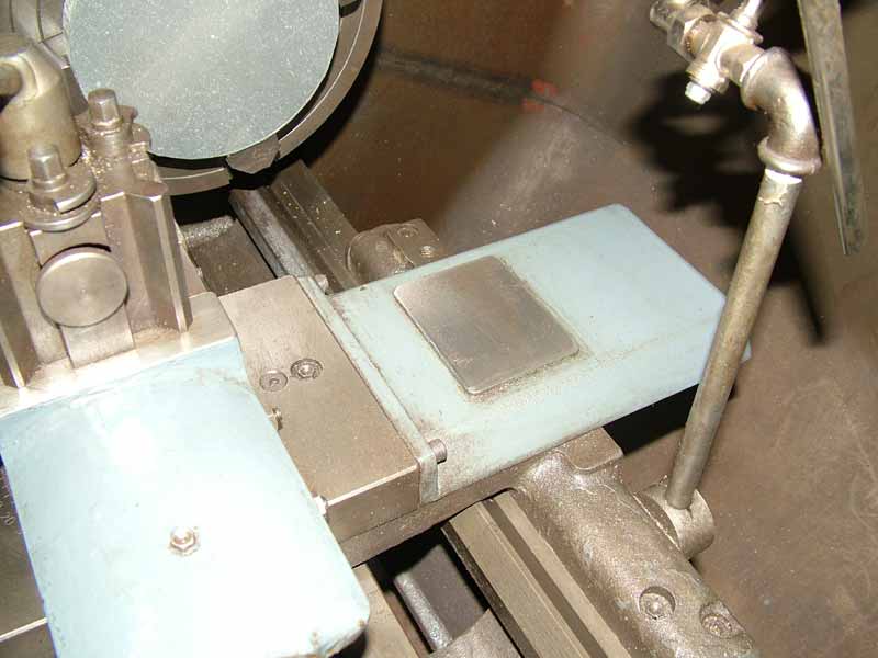
The cross-slide back cover on my machine is of cast aluminium alloy and consequently makes mounting a DTI (dial test indicator) with magnetic base rather difficult - if you mount it on the section just behind the tool-post, there is little room to work. A while back I made this very simple mild steel plate and simply stuck it on with Sikaflex - it's still stuck fast 10 years on!
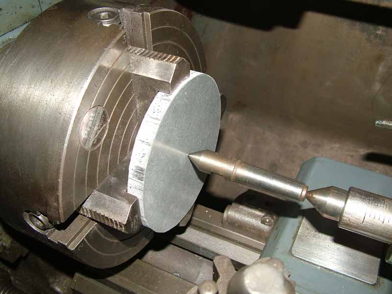
This shows the 'dummy' centre positioned between the tailstock centre and the alloy plate, prior to true-ing using the DTI - one important word of caution when employing this method is that you MUST get the job fairly close by eye before adding the loose centre. If it was used when the job was a long way out of true with a noticeable angle on the dummy, then as it is brought central it will put undue axial load on the job and the tailstock.
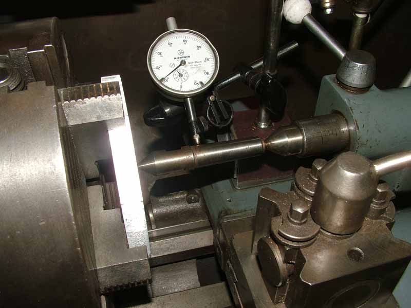
With the DTI plunger resting on the 'dummy' centre, preferably a bit nearer the work-piece than I have shown it here to get the maximum accuracy, it's a normal 4-jaw setting job from now on. When the job is accurately centred, the dummy centre is removed and the centre drill mounted in the tailstock. Next job will be large centre hole with a register to locate on the chain-case mounting adaptor.
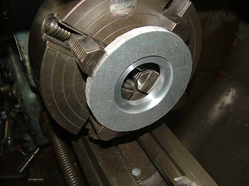
The internal diameter is not critical, but the register diameter and depth are - the alternator stator has only a small clearance over the rotor and this clearance should be equal all round (the 'Air-Gap') with no possibility of the two touching.
I have seen many alternator rotors (and stators) on British bikes with all kinds of surface damage - it could be from careless assembly, bent crank ends or distorted mounting cages - which are quite flimsy anyway, or a combination of any of these. I have said many times during this build-up that I am trying to 'engineer' out as many faults as possible, and this is just another example. These bikes might have had the very best handling frame available, an almost bomb-proof engine and other desirables, but the fit of some of the stuff was very hit and miss - o.k. I will concede that they were produced without modern materials or cad/cam, but there is no harm in seeking achievable improvements where possible. I realise that any rivet counting purists reading this might be offended by these deviations from standard, but it's MY bike and I want to enjoy it and not have to carry my bus-pass with me whenever I venture out on it!
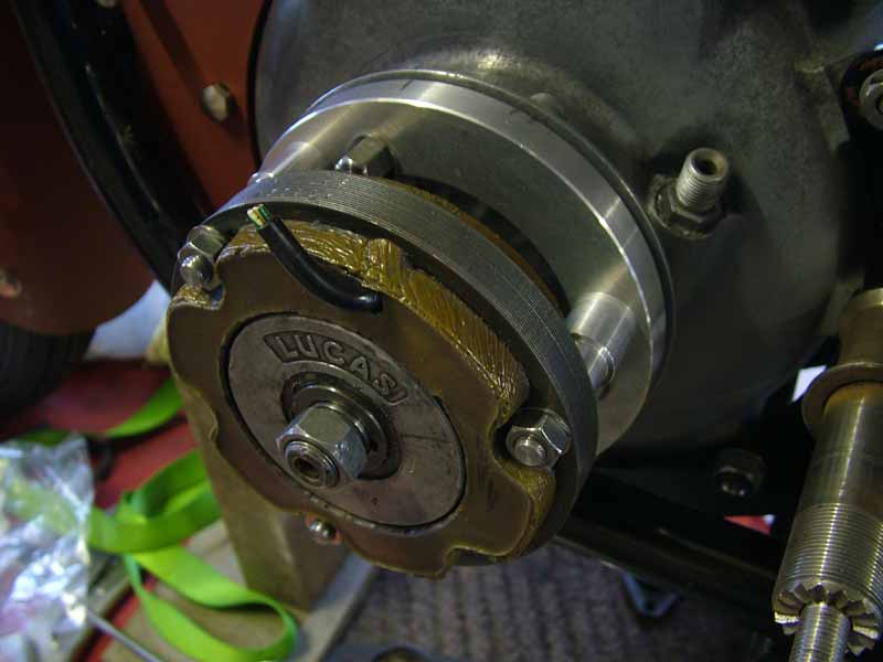
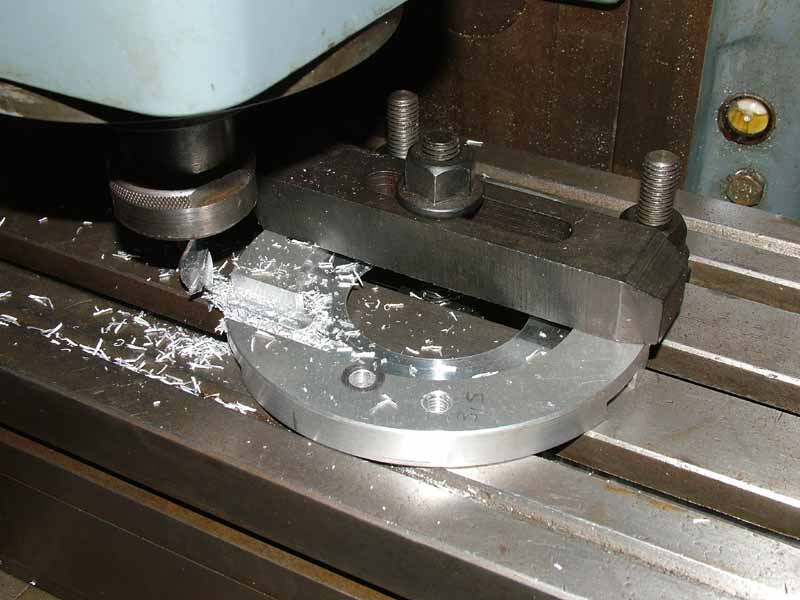
All fitted and checked, complete with spacers. It just needs a groove machining in the face to give a bit of clearance to the primary chain.
This was done on the miller, but typically I had to remove the horizontal arbor and fit the vertical head - why is everything the wrong way around when I want to do a job!
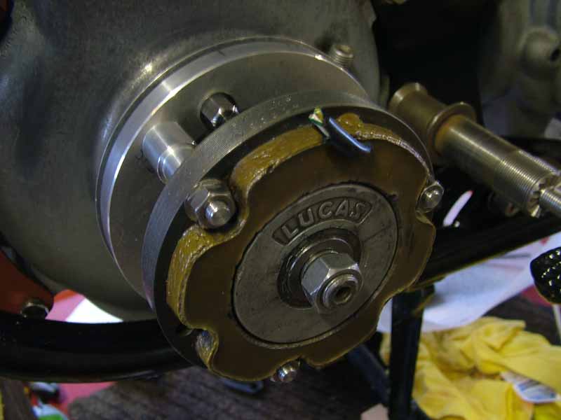
It was then just a normal assembly job
This shows the turned spacers to keep the stator in the correct position.
Just the wiring to extend by re-soldering and sleeving