A Simple Tinman's Hand Jenny
Some time ago I was asked if I could help out with a machine for shaping the brass rings on a traditional Orkney 'Bride's Cog' These are a little bit like the hoops on a barrel, in that they are slightly conical in section to follow the angle on the Cog body. The Cog is a traditional drinking vessel still used at Orkney weddings. The recipe for the actual concoction it contains varies from family to family but can be a very potent brew, having very strange effects on one's ability to speak, walk or even stand if too much is consumed - not to mention the possibility of occasional floating dentures to contend with as it is passed from guest to guest!
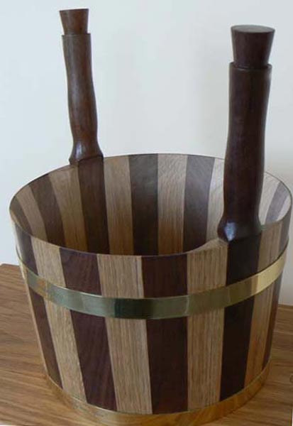
This shows the shape required for the brass hoops.
A normal Tinman's hand jenny, also called a swaging machine would probably do the job with the right shape of wheels, but they are rather difficult to find now and very expensive when they do occasionally appear on eBay. All that is really required of this machine is that one edge of the hoop can be slightly squeezed to effectively make it thinner. This in turn makes the thinned edge longer in circumference than the 'unthinned' edge and on a ring of this type, gives the required taper. Some experimentation will be required to get just the right amount of thinning in order to be a snug fit on the woodwork.
I looked around the workshop and found a suitable piece of 4x2 steel box section and lopped a piece off using the angle grinder with a thin cutting disc.
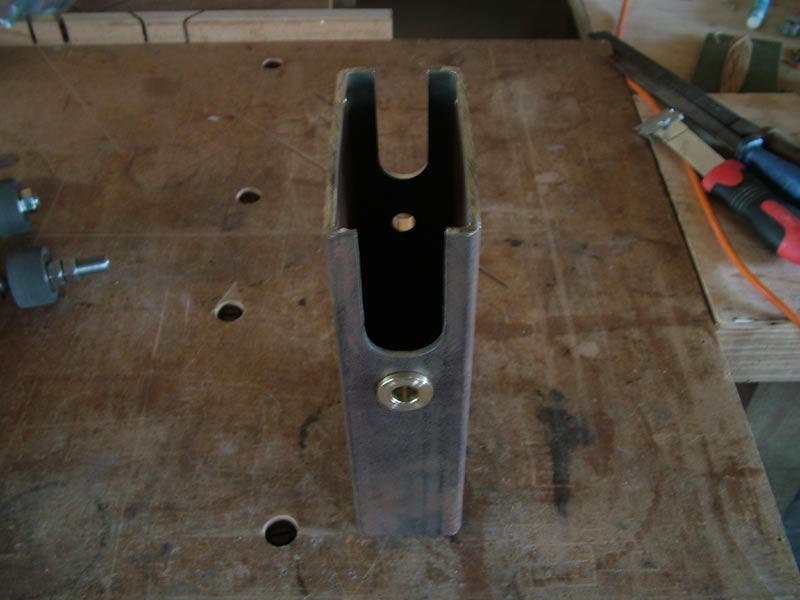
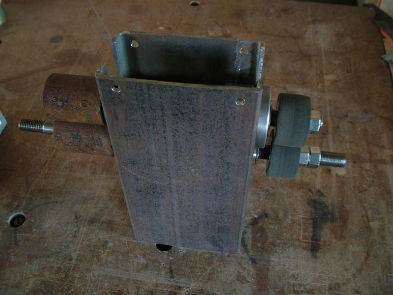
This is the main body with the pressed in phosphor bronze bushes for the lower shaft and the cut-outs for the upper adjustable shaft bearing blocks. The cut-outs were produced by chain drilling the curves and then chopping out the waste using the thin angle grinder disc again.
If there is no drive between the rollers and you merely rely on the friction between the rollers and the work piece, then under load there can be some slippage. In the case of a polished brass hoop, this would usually mean marks and scratches appearing on the finished piece. Ideally there needs to be a pair of contra-rotating gears at the opposite end to the forming rollers and although I have a set of involute cutters for my milling machine, they are of 16DP form and as such would not give much depth of tooth when raising and lowering the top shaft for pressure adjustment. I decided to try a pair of hard rubber rollers to take the place of the gears - we'll see how they perform. I have trapped the rubber rollers between 2 washers and nuts, so that some compression can be applied to increase the roller diameters.
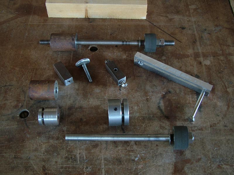
These are some of the component parts of the machine, the rusty steel rollers have yet to have their o/d's machined to size and finish.
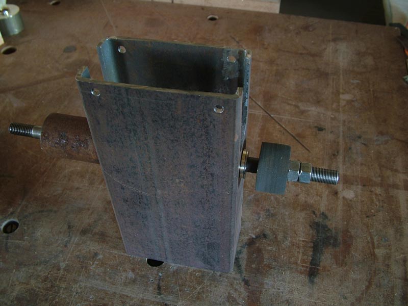
Assembly begins with the lower shaft through the bushes.
......followed by the top shaft with its support trunnions.
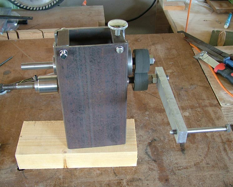
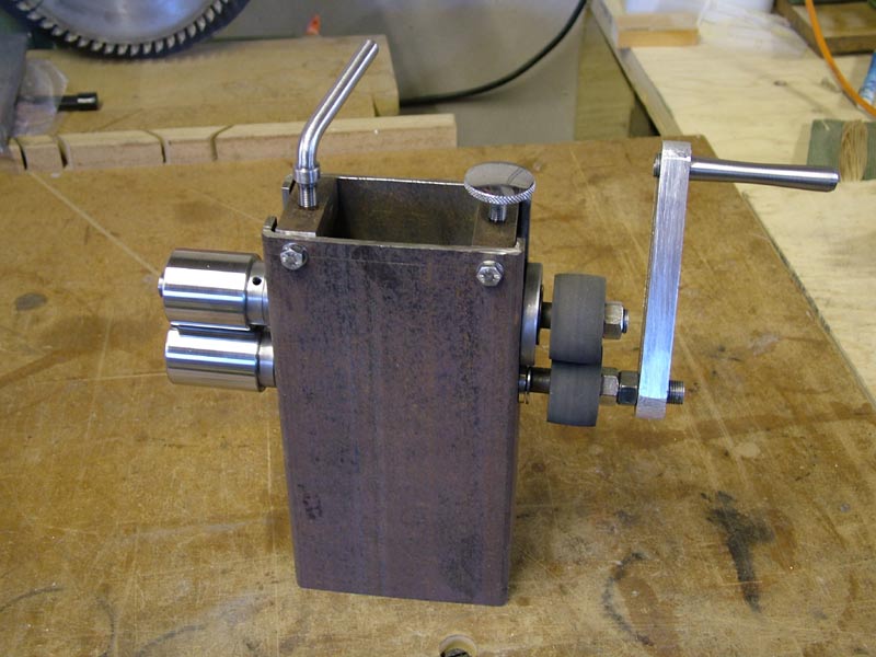
Next are the top blocks for the rubber roller adjuster and the operating handle. The knurled adjuster on the right was found in the box of 'stuff that might come in handy one day' - see, told you I would need it! The aluminium crank handle needs a bit of thinning and smoothing, plus a proper handle to turn it with instead of the Gold Wing seat bolt! By adjusting the compression on the rubber rollers the angle between the forming rollers will change and (hopefully) by varying the pressure on one edge of the brass hoop, will produce the taper. The top block on the right will be drilled and tapped for the adjusting lever for clamp pressure.
In actual fact the hoop required is really the frustum of a cone. (a paper drinking cup is the frustum of a cone with a bottom attached) and as such could be drawn out and developed from a flat sheet and just rolled into the required shape. The main problem with that method is that there is quite a lot of waste, as the parallel strip becomes a slow arc.
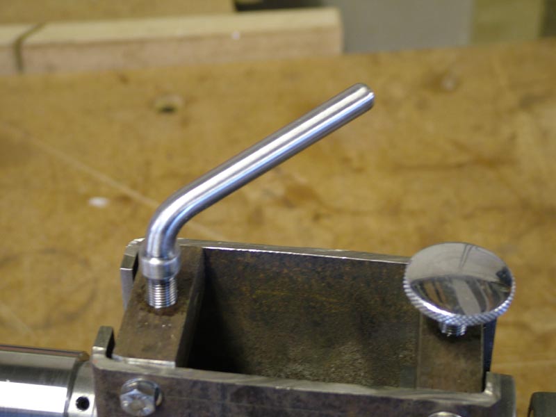
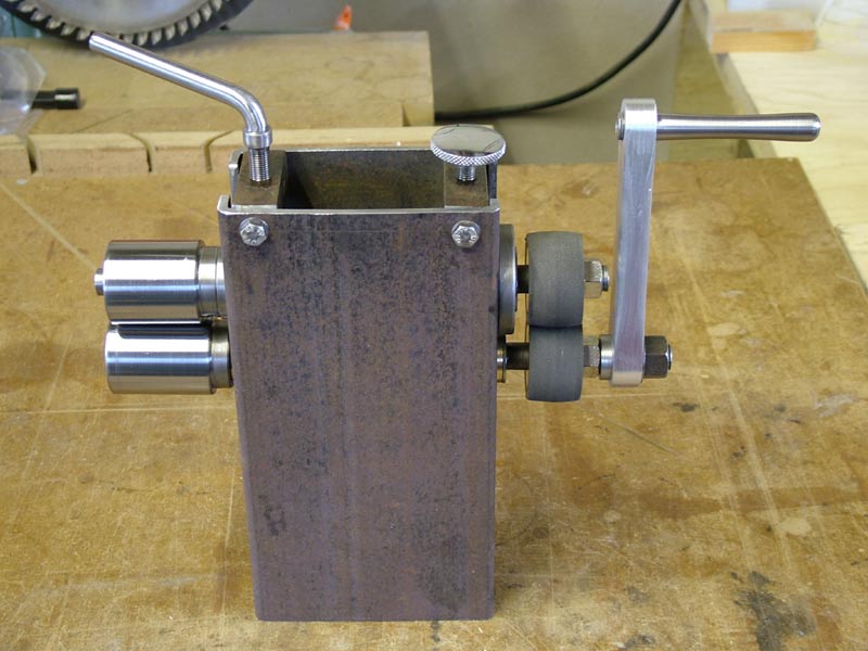
The threaded adjuster handle in place, made in one chucking op. on the lathe and then heated and bent to a suitable angle to clear the other adjuster knob.
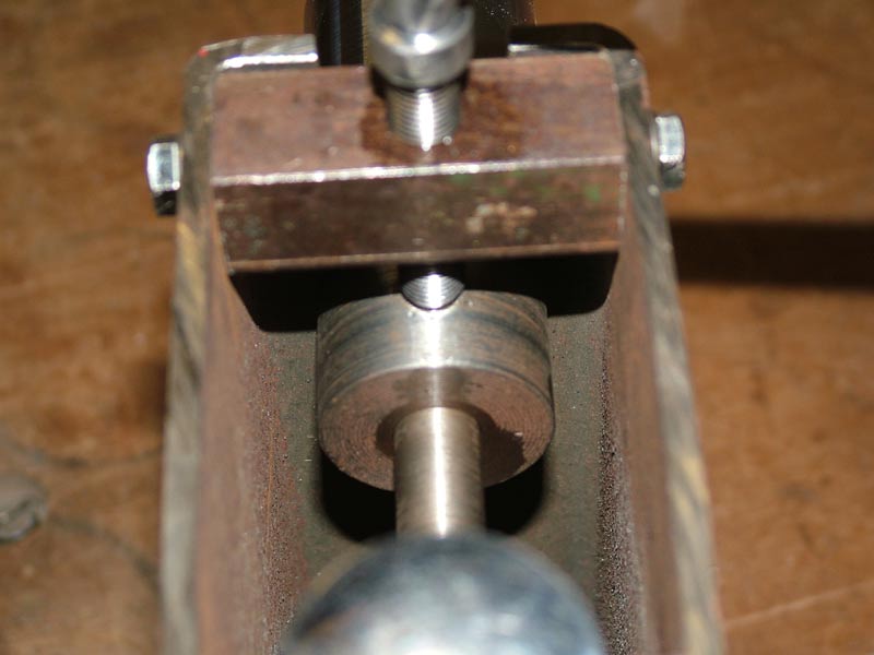
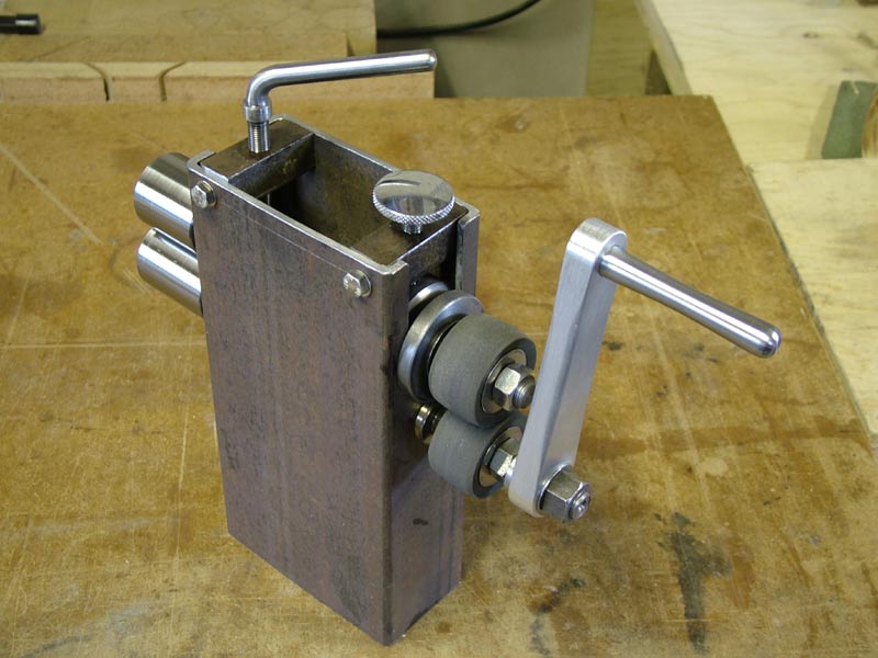
There is a small spigot on the end of the adjustment lever which locates in a hole in the trunnion, preventing same from rotating in the housing.
It just needs a bit of tidying - I'll see if I can get hold of a strip of the right thickness of brass to test the function and modify if necessary. As I have gone along making this unit in spare time between other jobs, I have also been roughing out another set of components so that I can make one for myself. I can also make spare sets of wheels to turn it into a proper Jenny for grooving and flanging strips and cylindrical components.
Everything seems to function correctly so after a test it's off to be used in Sanday for the real thing. I would quite like to make a Cog - just for the hell of it. I have some light oak, but no really dark contrasting wood to go with it.